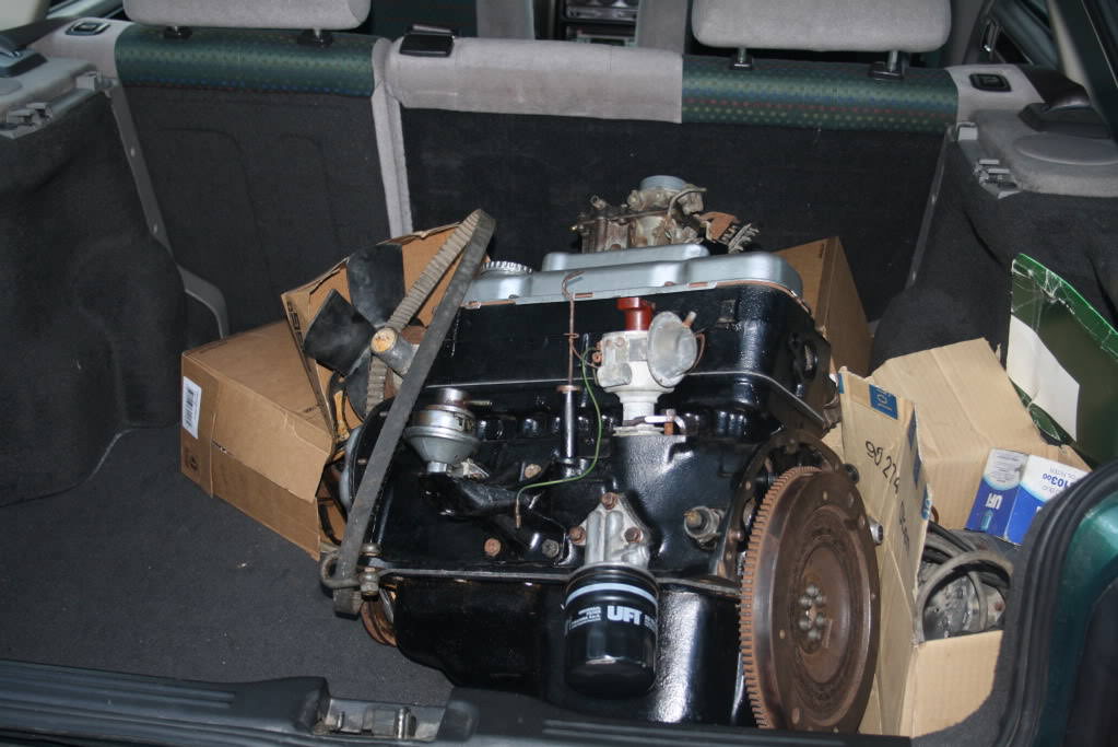
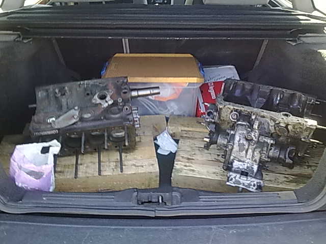
Finalmente encontrei o referido artigo do David Vizard. Sei que é extenso mas acho que perante as imagens anteriores, vale bem a pena lêr.
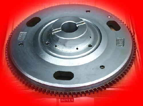
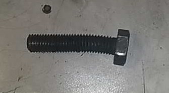
When the 1275 GT was introduced in 1969, this as such, did not have an engine. However, early ones were often built using existing factory stock and a number of early 1275 GTs were equipped with either a tuftrided ‘S’-type crank (some of which had 1300 centre main bearing widths) and ‘S’ rods, an ‘S’ crank and Midget rods, or the then newly introduced big journal cranks and EN19 rods. The big journal cranks and EN19 rods are the most common combination, and generally referred to as 1300 cranks and rods. The rods I have already described. The 1300 rods are the ones with the big balance pads on, and the 1300 cranks were made from EN16T and non heat treated, the extra strength being made up by having a 1 3/4 inch big end instead of a 1 5/8 inch big end.
When the Metro was originally envisaged, it was deemed necessary for two reasons that the power level of the Series ‘A’ engine would have to be raised to keep the performance of the new car in line with then current standards and to compensate for the fact that the Metro would, in all probability, be a heavier car than the Mini. This requirement led to much development work being undertaken in terms of improving long term reliability of the engine at these new, higher power levels.
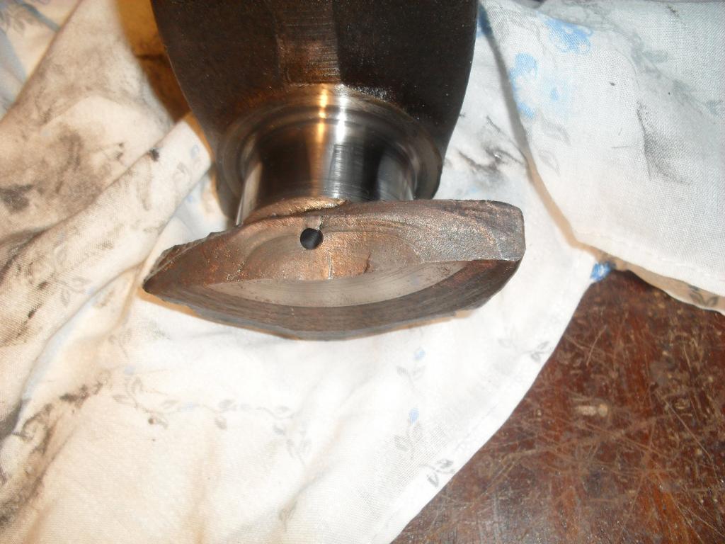
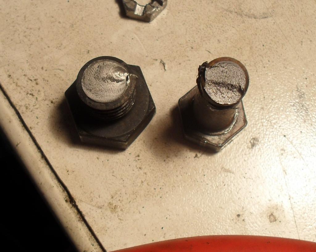
Much of this work was done on the crankshaft. With the start of the Series ‘A+’ engine development, cranks were initially taken straight from the 1275 GT line, but under endurance tests these cranks developed fatigue problems in the fillet radius, that’s the radius between the big end or main bearing journal and the cheek of the crank web. Testing revealed that if the cranks were not made exactly to drawing spec, they would fall in the fillet radius.
The most common failure was between number 4 big end and the main bearing nearest the tail of the crank. The second most common failure was between number 1 big end and number 1 main bearing. The third most common failure was from number 1 main bearing through the web that joins number 1 to number 2 big end.
Tests showed that almost all these failures were the result of too small a fillet radius. Usually it was too small because it was outside production tolerances. Unfortunately a lot of cranks left the factory like this. However, I think I should make the point here that the tests Leyland conduct on their cranks to see if they have adequate fatigue life are very arduous. It amounts to driving the engine at maximum rpm under full throttie for 100 hours or more. This is roughly equivalent to 10,000 miles of flatout motoring at maximum rpm on the motorway. Cranks that did break tended to do so near the end of the test.
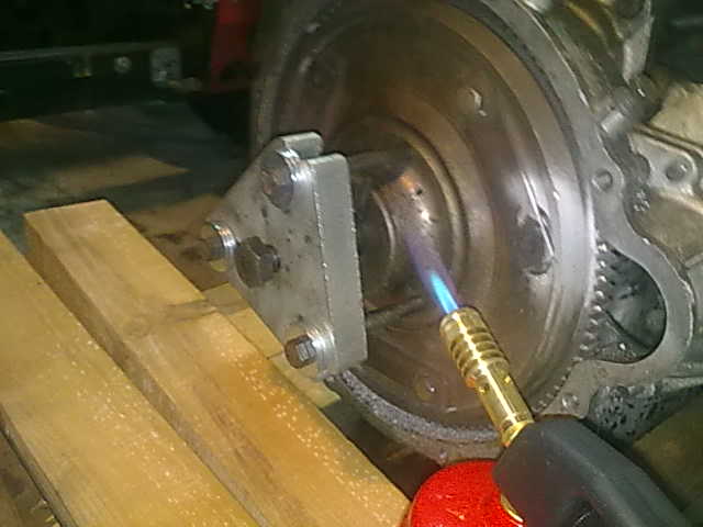
On the other hand, cranks that were made to drawings would complete the test without faiiure. These would often run as far as 50,000 miles before they finally broke. The obvious solution to such crank breakage (as the factory engineers well knew) was tuftriding, however, though a known cure to the problem, the tuftriding process, at the time, was causing controversy because of the atmospheric pollution it causes. Very stringent regulations were being laid down relating to when and where tuftriding plants could be built and operated. As a result of the environmental problems Leyland decided to investigate the potential fillet radius cranks.
This process which had been used successfully by Ford, BMW and many other big manufacturers to increase crankshaft fatigue life For instance, on a 2000cc. overhead cam Ford engine, rolled proved to extend the fatigue life by a factor of at least 100%.


 D
D